Kaydon Gravity Oiler Model 4b
 Description
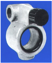
The Gravity Sight Feed Oiler affords a clear view and fine control of oil flowing, by gravity, to a lubrication point. The double window design permits observation of the oil stream from either side of the oiler.
Download Product Information PDF for more details.
Features
- Body vent prevents the fogging of the windows.
- Optional single installation; or oilers may be manifolded in batteries to form a central lubrica- tion control point. They are especially useful for equipment having many lubrication points.
- Cast iron body construction with glass windows, bronze fittings and a blue enamel finish.
- Maximum working pressure of 125 psi at the maximum operating temperature of 225°F.
- Flow through the oiler is relative to the adjust- ment of the screw for various viscosities of oil at different supply pressures.
Applications
- Paper Mill Oiling Systems
- Steam Engines
- Gas Engines
- Related Industrial Applications.
Installation
The Model 4B Oiler must be installed in a vertical position, as shown in the drawing on page 2. To facilitate service and prevent possible starvation of lubricant to a bearing, no more than four oilers should be manifolded together. When the oiler is located at the end of the supply manifold, i.e. with no equipment installed on the downstream side of the oiler, the unused connection must be closed with a suitable ½“ pipe plug.
Operation
Start the flow of oil through the system. Turn the oiler adjusting screw (1) to open the oiler. Adjust the screw until the described flow is obtained. Use the accompanying graphs (see page 2) as a guide to the adjustment of the oiler.
Note: Adjust the oiler by hand only. Never use wrenches, etc., to turn the adjusting screw.
Maintenance
This oiler should give trouble-free service with little or no maintenance required. It may be desirable to clean the win- dows periodically. To do so, close the adjusting screw to stop the flow through the oiler. Insert a pointed tool into the hold in the body (X) to push the “O” ring (7) away from the body. By pulling the loop thus formed, the “O” ring may be easily withdrawn from the body. To facilitate the removal of the glass window, touch a piece of adhesive tape to the glass and pull gently. Clean glass with a soft cloth. Inspect “O” ring and replace if worn or damaged. Reassemble parts in reverse sequence.
We have over 18 years experience in helping our customers find the products that they need, at prices that they can afford, when they need them. Let us help you too!